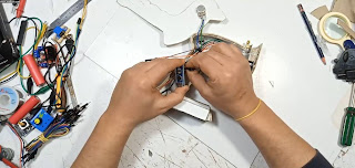
السلام عليكم ورحمة الله وبركاته اصدقائى الاعزاء
يسعدنى ان اطرح عليكم فكرة مشروع جهاز تحكم عن بعد ولكن فى هذا المشروع سوف احاول جاهدا
ان ابسط لكم الامور بقدر الامكان
لذالك اليوم لن نستخدم اى ادوات مساعده مثل مكواة اللحام او لوحات النحاس المستخدمة فى طباعة البوردات الالكترونية
وايضا سوف اقوم باستخدام كود برمجى تم استخدامة من قبل فى عمل المرسل ل 7 قنوات وبالتالى من قام بتحميل الكود
مسبقا لن يحتاج الى تحميل هذا الكود المستخدم كما اننى ساقوم بتقليل عدد القنوات وذالك لتسهيل عملية التوصيل بين القطع
المختلفة
واما عن القطع المستخدمة فى هذا المشروع
1- لوحة nrf24l01-wireless-module-with-antenna لوحة اتصال عن بعد
2-لوحة arduino-nano اردوينو نانو او اى نوع متوفر
3- joystick-module-for-arduino عصى تحكم
4- Potentiometerمقاومة متغيرة
5- مفتاح 3 طرف
روابط شراء القطع
على فكرة انا لم استخدم فى هذا المشروع اشياء معقدة فقط قمت بالتوصيل بين القطع عن طريق الاسلاك فقط والريموت كنترول عباره عن 3 شانل اى فقط 3 قنوات يمكن للجميع تنفيذه بكل سهوله
والان يمكنك مشاهدة هذا الفيديو لمتابعة تفاصيل المشروع ولكن اولا لاتنسى الصلاة على النبى محمد {صلم}
وايضا ادعوك لمتابعة قناتى على يوتيوب من خلال الضغط هنا
يمكن نسخ الكود من هنا ايضا
المرسل
----------------------------------------------------------------------------------------
/* Tranmsitter code for the Arduino Radio control with PWM output
* Install the NRF24 library to your IDE
* Upload this code to the Arduino UNO, NANO, Pro mini (5V,16MHz)
* Connect a NRF24 module to it:
Module // Arduino UNO,NANO
GND -> GND
Vcc -> 3.3V
CE -> D9
CSN -> D10
CLK -> D13
MOSI -> D11
MISO -> D12
This code transmits 7 channels with data from pins A0, A1, A2, A3, D2 and D3
*/
#include <SPI.h>
#include <nRF24L01.h>
#include <RF24.h>
const uint64_t my_radio_pipe = 0xE8E8F0F0E1LL; //Remember that this code should be the same for the receiver
RF24 radio(9, 10); //Set CE and CSN pins
// The sizeof this struct should not exceed 32 bytes
struct Data_to_be_sent {
byte ch1;
byte ch2;
byte ch3;
byte ch4;
byte ch5;
byte ch6;
byte ch7;
};
//Create a variable with the structure above and name it sent_data
Data_to_be_sent sent_data;
void setup()
{
radio.begin();
radio.setAutoAck(false);
radio.setDataRate(RF24_250KBPS);
radio.openWritingPipe(my_radio_pipe);
//Reset each channel value
sent_data.ch1 = 0;
sent_data.ch2 = 127;
sent_data.ch3 = 127;
sent_data.ch4 = 127;
sent_data.ch5 = 0;
sent_data.ch6 = 0;
sent_data.ch7 = 127;
}
/**************************************************/
void loop()
{
/*If your channel is reversed, just swap 0 to 255 by 255 to 0 below
EXAMPLE:
Normal: data.ch1 = map( analogRead(A0), 0, 1024, 0, 255);
Reversed: data.ch1 = map( analogRead(A0), 0, 1024, 255, 0); */
sent_data.ch1 = map( analogRead(A0), 0, 1024, 255, 0);
sent_data.ch2 = map( analogRead(A1), 0, 1024, 0, 255);
sent_data.ch3 = map( analogRead(A2), 0, 1024, 0, 255);
sent_data.ch4 = map( analogRead(A3), 0, 1024, 0, 255);
sent_data.ch5 = digitalRead(2);
sent_data.ch6 = digitalRead(3);
sent_data.ch7 = map( analogRead(A4), 0, 1024, 0, 255);
radio.write(&sent_data, sizeof(Data_to_be_sent));
}
---------------------------------------------------------------------------------------------------------------------------
كود المستقبل
--------------------------------------------------------------
/* Receiver code for the Arduino Radio control with PWM output
* Install the NRF24 library to your IDE
* Upload this code to the Arduino UNO, NANO, Pro mini (5V,16MHz)
* Connect a NRF24 module to it:
Module // Arduino UNO,NANO
GND -> GND
Vcc -> 3.3V
CE -> D9
CSN -> D10
CLK -> D13
MOSI -> D11
MISO -> D12
This code receive 7 channels and create a PWM output for each one on D2, D3, D4, D5, D6, D7and D8
*/
#include <SPI.h>
#include <nRF24L01.h>
#include <RF24.h>
#include <Servo.h> //To create PWM signals we need this lybrary
const uint64_t pipeIn = 0xE8E8F0F0E1LL; //Remember that this code is the same as in the transmitter
RF24 radio(9, 10); //CSN and CE pins
// The sizeof this struct should not exceed 32 bytes
struct Received_data {
byte ch1;
byte ch2;
byte ch3;
byte ch4;
byte ch5;
byte ch6;
byte ch7;
};
Received_data received_data;
Servo channel_1;
Servo channel_2;
Servo channel_3;
Servo channel_4;
Servo channel_5;
Servo channel_6;
Servo channel_7;
int ch1_value = 0;
int ch2_value = 0;
int ch3_value = 0;
int ch4_value = 0;
int ch5_value = 0;
int ch6_value = 0;
int ch7_value = 0;
void reset_the_Data()
{
// 'safe' values to use when NO radio input is detected
received_data.ch1 = 0; //Throttle (channel 1) to 0
received_data.ch2 = 127;
received_data.ch3 = 127;
received_data.ch4 = 127;
received_data.ch5 = 0;
received_data.ch6 = 0;
received_data.ch7 = 127;
}
/**************************************************/
void setup()
{
//Attach the servo signal on pins from D2 to D8
channel_1.attach(3);
channel_2.attach(8);
channel_3.attach(4);
channel_4.attach(5);
channel_5.attach(6);
channel_6.attach(7);
channel_7.attach(2);
//We reset the received values
reset_the_Data();
//Once again, begin and radio configuration
radio.begin();
radio.setAutoAck(false);
radio.setDataRate(RF24_250KBPS);
radio.openReadingPipe(1,pipeIn);
//We start the radio comunication
radio.startListening();
}
/**************************************************/
unsigned long lastRecvTime = 0;
//We create the function that will read the data each certain time
void receive_the_data()
{
while ( radio.available() ) {
radio.read(&received_data, sizeof(Received_data));
lastRecvTime = millis(); //Here we receive the data
}
}
/**************************************************/
void loop()
{
//Receive the radio data
receive_the_data();
//////////This small if will reset the data if signal is lost for 1 sec.
/////////////////////////////////////////////////////////////////////////
unsigned long now = millis();
if ( now - lastRecvTime > 1000 ) {
// signal lost?
reset_the_Data();
//Go up and change the initial values if you want depending on
//your aplications. Put 0 for throttle in case of drones so it won't
//fly away
}
ch1_value = map(received_data.ch1,0,255,1000,2000);
ch2_value = map(received_data.ch2,0,255,1000,2000);
ch3_value = map(received_data.ch3,0,255,1000,2000);
ch4_value = map(received_data.ch4,0,255,1000,2000);
ch5_value = map(received_data.ch5,0,1,1000,2000);
ch6_value = map(received_data.ch6,0,1,1000,2000);
ch7_value = map(received_data.ch7,0,255,1000,2000);
//Creathe the PWM signals
channel_1.writeMicroseconds(ch1_value);
channel_2.writeMicroseconds(ch2_value);
channel_3.writeMicroseconds(ch3_value);
channel_4.writeMicroseconds(ch4_value);
channel_5.writeMicroseconds(ch5_value);
channel_6.writeMicroseconds(ch6_value);
channel_7.writeMicroseconds(ch7_value);
}//Loop end


ممكن رقم الهاتف مروري لو سمحت
ردحذفالسلام عليكم ورحمة الله وبركاته
ردحذفكيف حالك يا اخ أشرف
لو سمحت ممكن اعرف كم مقدار مسافة التحكم عن بعد لهذا الجهاز
تقريبا بدون عوائق طبيعية او صناعية مثل الجبال والمباني تصل الى 1100 متر يعنى اكثر من واحد كيلو متر
حذف